
Binospec IFU information
The Binospec Integral Field Unit
An Integral Field Unit (IFU) for Binospec has been built and was commissioned by the SAO instrument team in the Fall 2023 semester. First light through the IFU was obtained in December 2023. The IFU is available for general observing in 2024 and onward. This page describes the properties of the IFU as designed. Please note that all information is subject to change and updating as we gain experience with the IFU.
Dan Fabricant has published a PASP paper describing the Binospec IFU: An Integral Field Unit for the Binospec Spectrograph, Fabricant et al, 2025, PASP, 137, 5002. Please see this paper for more information and consider citing it when you publish IFU data.
Construction
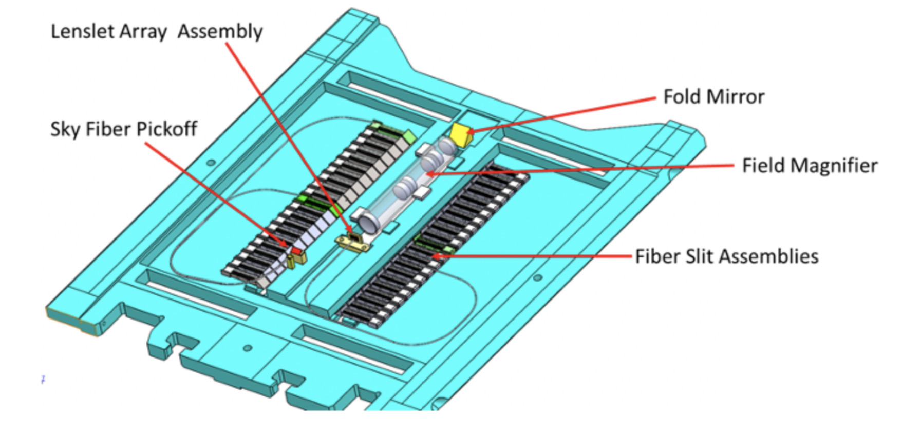
The IFU is built into a unit, shown above, that is inserted into the instrument like a slitmask, near the focal plane of the telescope. The cyan section is a modified slitmask frame. A pickoff mirror (yellow) redirects light from the science field into magnifying optics (gray), then into a lenslet array, and optical fibers, which remap the field into pseudo-longslits on the two spectrographs of Binospec. A second, smaller pickoff mirror samples a sky area roughly 8 arcminutes from the field. The light from the fibers enters the Binospec collimators and is dispersed and imaged onto the detectors as if from a longslit.
Binospec IFU properties
The Binospec IFU allows measuring spectra over a spatially 2-D area, a single rectangular science field of 16.5 x 12 arcseconds. There is one small separate, spatially offset sky field. The spatial elements (spaxels) are defined by hexagonally packed lenslets, 0.6 arcsec across on the sky, with almost 100% filling factor (without gaps, 0.6 arcsec side-to-side, 0.8 arcsec corner-corner). The IFU field of view is a rectangle longways east-west, so for a sky position angle of 0, the field spans 16.5″ E-W and 12″ N-S (“landscape” orientation on the sky).
There are 720 fibers in total, 640 on the science and 80 on the sky fields. The spatial elements are remapped into pseudo-long-slits and dispersed by the usual Binospec optics, with spectral resolution and coverage roughly similar to using an 0.7″ wide longslit. The data images contain roughly 720 individual spectra, 360 in each side of Binospec, lined up in pseudo-slits, as if each side of Binospec had a longslit with hundreds of elements in the slit.
For example, since the spectral resolution is set by the ~0.7″ spatial element, the resolution of the spectra will be about R ~ 1700, 5100, 5600 for the G270, G600, G1000 gratings respectively. (In practice it is measured at a little higher, and is also a function of wavelength, higher resolution at redder wavelengths.) The wavelength coverage is as shown in the table on the main Binospec page. The allowed central wavelength settings are somewhat different than for the longslit, because this depends on the availability of a spectral line to the flexure control system at the requested grating angle.
The Binospec IFU spatial sampling of ~0.6-0.7 arcsec is well matched to typical seeing at the MMT and is large compared to other microlens IFUs, such as the GMOS IFU (0.2 arcsec). Thus, it is expected that the IFU will be more useful for low surface brightness observations than a high-spatial sampling fiber IFU, and may be able to do projects that are typically in the realm of image-slicer IFUs such as Keck/KCWI or VLT/MUSE. (With the caveat that the field of view and spectral coverage are not direct equivalents of either KCWI or MUSE and the sensitivity is not yet calibrated.)
IFU throughput, sensitivity, sky subtraction quality, and so on will be updated once commissioning data is available. The throughput per fiber appears to be roughly uniform to 5-10%, apart from about 4 broken fibers. The throughput losses in the fiber system are not precisely quantified yet but probably 30-50 percent; balanced against this, the IFU suffers less slit loss than a longslit in typical seeing.
Observing procedures
The Binospec IFU is inserted like a Binospec multi-slit mask, but requires careful handling. It is likely that the IFU will stay in the instrument semi-permanently as long as it sees many requests for use. But since there are limited slots for masks, the IFU could in principle not be installed, and PIs must request it ahead of time. For example, a target of opportunity observation should not yet request the IFU unless this has been previously discussed with MMT staff.
Although it is in principle possible to spatially dither IFU observations, or to spatially offset pointings to create larger mosaics, these modes are not fully supported and we do not recommend trying to dither or mosaic within a single IFU target. It is not clear that spatial dithering is necessary or improves the data product, and it is not currently supported by the pipeline. If you ask for dithered data in a single observing block, the default reduction will combine exposures in the same fiber even though they are at different spatial positions, which is undesirable. If you absolutely want to spatially dither, we recommend that you create separate targets for each position (eg 3 separate targets offset in a triangle 1.5 spaxels on a side), so that each position can be combined and reduced independently, and then you can figure out how you want to combine the reduced datasets into a cube.
If you want to create an IFU map over an area larger than the IFU field, you should create separate targets for each pointing, and anticipate that they will be reduced into separate datacubes.
Creating IFU targets
PIs can request the IFU in their MMT observing catalog forms, similar to how one chooses a longslit. Target acquisition is similar to the longslit, where the PI specifies the RA, Dec, and position angle (PA), and does not need to select guide stars manually. Binospec chooses the guide stars itself to set the target onto the IFU. However, PIs should be aware that the PA is not completely free:
- 1. Guide stars cannot always be found for a fixed PA, so allowing a range of position angles will give the observers more chances for a successful acquistion (eg specify PA=+25 but write in the target notes “a range of +/-10 deg in PA is acceptable”).
- 2. There are rotator limits near +/-180 in rotator angle. To avoid these, use a sky PA that is closer to 0 (ie within -90 to +90) for targets south of the MMT, Dec<+33; use a sky PA closer to +/-180 for targets north of the MMT, Dec>+33.
The average overhead time required for an IFU observation is similar to other spectroscopic observations, and the current estimate used in the scheduler is the same as for a longslit or slit mask spectroscopic observation: an estimated 30 minutes for acquisition, calibration exposures, CCD readout, etc.
IFU data format
The format of IFU images in the raw data is like the non-IFU data: you get files named sci_img_*.fits that have FITS extensions for each CCD amplifier, and sci_img_*_proc.fits that are bias subtracted and reassembled into 2 FITS extensions, one for the side A CCD and one for side B CCD. The proc images are easier to look at, the unproc images are what the pipeline runs on.
The format of the IFU raw data, most easily seen in the sci_img_*_proc.fits images, is that on each of the 2 sides of Binospec (2 fits extensions), there are spectra from 16 groups of 20 science fibers, with 5 groups of 8 sky fibers in between. The sky fibers are identifiable because they are in groups of 8 and the sky level of the spectra is brighter (the sky fibers subtend a larger diameter on sky). The mapping of spectra on detector to fiber location on sky is given in the file “calib_Bino/IFU/bino_IFU_sky_layout.fits”, which you can retrieve by checking out the ifu-dev branch of the pipeline as described below.
IFU data reduced by the pipeline is described briefly at the Binospec pipeline wiki under Reduced data formats. Reduced IFU data includes files called: “obj-sky_fib_lin.fits” that contains each fiber (lenslet, spatial element) spectrum, one per row, and a table of mapping from fiber to on-sky location; and “obj-sky_cube.fits” that assembles the spectra into a datacube. Since the layout of fibers is hexagonal, not cartesian, the cube is resampled spatially, and science analyses sensitive to this may need to use the individual spectra.
IFU data processing
Binospec IFU data are reduced by a new mode of the existing Binospec pipeline. This mode has been tested with commissioning data obtained in 2023 and 2024, and details on the data products are briefly described above.
As of December 2024, the SAO TDC team is now reducing IFU data regularly and returning data to PIs through the MMTO catalog interface, similarly to reduced data for longslits and slitmasks, although the data format is different for the IFU cube. PIs should get reduced data notification emails. Reduction is still a manual process and some datasets give more difficulty, so if you don’t see reduced data, you can contact an MMT instrument scientist to ask.
To try running the Binospec IFU pipeline, you can follow the pipeline instructions at Binospec pipeline wiki, with the additional need to retrieve the “ifu-dev” branch of the pipeline rather than the master branch. Roughly these commands should work:
# retrieve MMIRS pipeline - may need this for some dependencies
mkdir mmirs_pipeline
git clone https://bitbucket.org/chil_sai/mmirs-pipeline.git
cd ..
# retrieve Binospec pipeline
mkdir bino_pipeline
cd bino_pipeline
git clone https://bitbucket.org/chil_sai/binospec.git
# get the ifu-dev branch
cd binospec
git checkout origin/ifu-dev
You then still need to have these directories in your IDL_PATH environment variable and set up other env variables as described on the Binospec pipeline wiki page. The pipeline is intended to detect from a header field that your images use the IFU, and should run in IFU mode. As mentioned above, the “bino_IFU_sky_layout.fits” file tabulates the translation from fibers to on-sky positions.