Selected Instrument


The central wavelength determines the mid-point of the signal to observation. You should try and make this the same as you would for actually observations to get the most meaningful exposure time or signal to noise estimate.
The following slits widths are available for Red and Blue Channel. As a rule of thubm, the median seeing at the MMT is on the order of 0.85".
| Slit Width (arcsec) | Blue FWHM (pixels) | Red FWHM (pixels) |
| 0.75 | 2.5 | 2.6 |
| 1.00 | 2.8 | 3.2 |
| 1.25 | 3.1 | 3.8 |
| 1.50 | 3.6 | 4.1 |
| 2.0 | 4.5 | 5.3 |
| 3.5 | 7.9 | 10.0 |
| 5.0 | 11.5 | 16.0 |
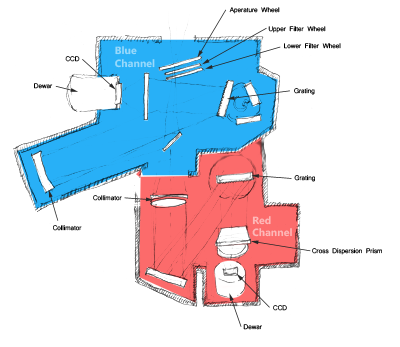
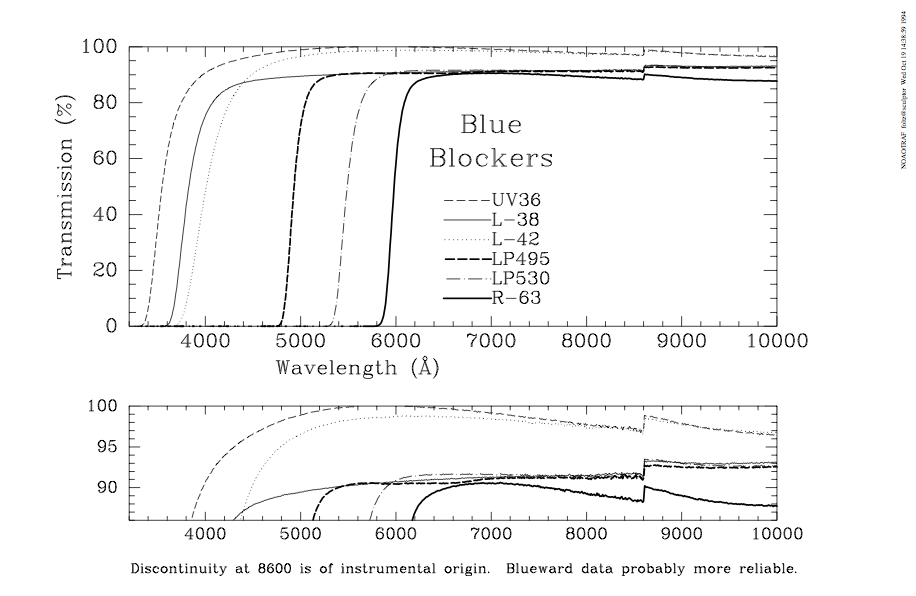
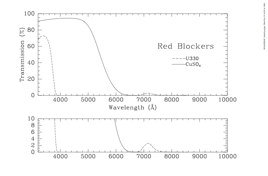
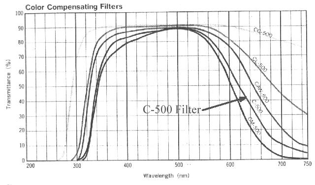
The f/9 topbox has the following filters avaialble. If other filters are needed, significant advanced planning is required with MMTO staff.
Currently, calculations are performed assuming the target is flat if Fν (i.e. has a constant AB magnitude). These calculations assume a point source . This may impact the calculation if you are studying an extended source or a source wher the majority of its flux is arising due to emission lines rather than continuum.
The desired binning on the detector is required in order to properly treat the noise in the detectors itself (outside of shot noise). Typically, both Red and Blue Channel are operated using no binning (1) in the spectral direction and binning by 2 in the spatial direction. Unbinned pixels have a scale of 0.3" / pixel. Median seeing at the MMT is on the order of 0.85".s
Enter the lunar phase between -14 and 14 (lunar age from Observer's almanac). Recall that the new moon is at phase = 0, and the full moon is at +/- 14.
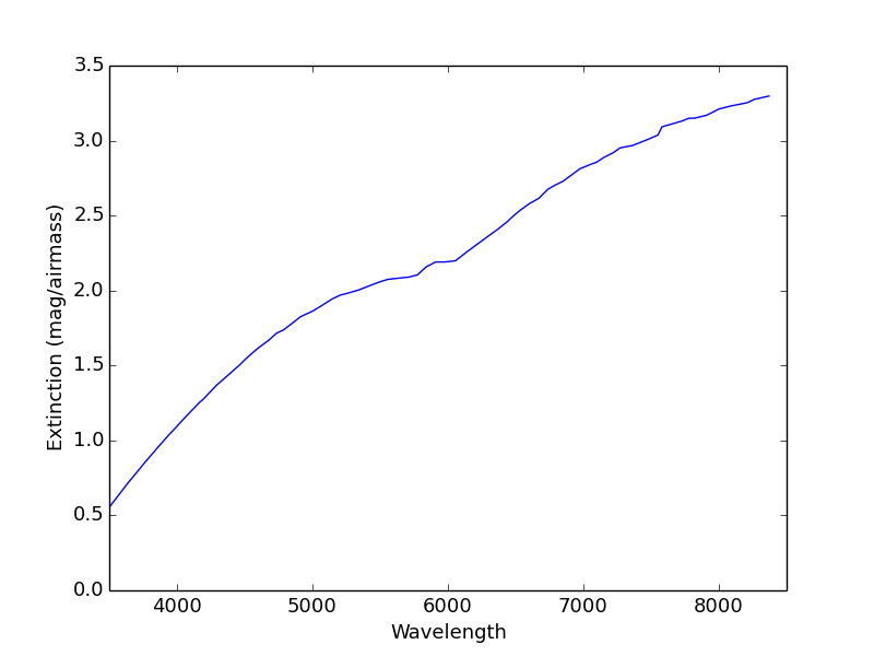
Clearly, the airmass at which an obseration is completed will have a significiant impact on the final signal to noise reached. Enter the mean airmass for your observations. A sample extinction curve is shown below.
The size of the seeing disk determines the fraction of the incoming source light that is lost by not making it through the slit. You need to specify the seeing you hope to achieve for your observations to estimate those slit losses. (Also, these calculations assume a point source . Extended sources may have higher losses).
Would you like to calculation the Integration Time (given a desired signal-to-noise ratio) or the Signal-to-Noise Ratio for an observation of a given exposure time?
Integration Time is the optimal observation time for an exposure based on the parameters you provide in the next step.
Signal-to-Noise Ratio is the quality the spectrum will obtain based on the parameters you provie and a fixed exposure time.
Enter the desired signal-to-noise value that you wish your exposure to reach. The convention of this calculator is the signal-to-noise per extracted pixel (summed across the spatial direction for a point source).
| Grating (lines/mm) | Order | Blaze Wavelength (Å) | R (@ Blaze, 1" slit) | Resolution (Å) | Dispersion (Å) | Coverage (Å) |
| 150 | 1st | 4800 | 230 | 21.0 | 6.37 | 6574 |
| 270 | 1st | 7300 | 640 | 11.4 | 3.59 | 3705 |
| 300 | 1st | 4800 | 460 | 10.3 | 3.21 | 3313 |
| 600 | 1st | 4800 | 960 | 5.0 | 1.63 | 1682 |
| 600 | 1st | 6310 | 1290 | 4.90 | 1.64 | 1692 |
| 1200 | 1st | 7700 | 3930 | 1.96 | 0.80 | 826 |
| 1200 | 1st | 9000 | 5097 | 1.77 | 0.78 | 805 |
| Grating (lines/mm) | Order | Blaze Wavelength (Å) | R (@ Blaze, 1" slit) | Resolution (Å) | Dispersion (Å) | Coverage (Å) |
| 300 | 1st | 4800 | 740 | 6.47 | 1.96 | 5268 |
| 500 | 1st | 5410 | 1430 | 3.79 | 1.19 | 3198 |
| 800 | 1st | 4050 | 1730 | 2.34 | 0.75 | 2016 |
| 600 | 1st | 9630 | 3330 | 2.9 | 1.0 | 2688 |
| 2nd | 4800 | 3310 | 1.45 | 0.50 | 1344 | |
| 832 | 1st | 7790 | 3830 | 2.04 | 0.72 | 1935 |
| 2nd | 3900 | 3830 | 1.02 | 0.36 | 968 | |
| 1200 | 1st | 4830 | 3340 | 1.45 | 0.50 | 1344 |